Iranian Classification Society Rules

< Previous | Contents | Next >
I. GENERAL
1. Application
(1) This guidance deals with the sloshing load occurred by the liquid in cargo tank and ship mo- tion in LNG carriers. This guidance applies to the assessment procedure and the acceptance cri- teria of cargo containment system under the sloshing load for the membrane LNG carrier.
(2) In addition, this guidance applies to the calculation procedure of the sloshing load for the ship with cargo tank beyond the application range of Rules for the Classification of Steel ships(here- inafter referred to as "the Rules" in this guidance), Pt 13, Sub 1, Ch 4, Sec 6, 6.
(3) This guidance applies the evaluation procedure for the sloshing load and the structural strength
of cargo containment system for marine LNG storage and regasification structures using the membrane technology.
(4) Requirement of this guidance shall apply in addition to the other requirement of the Rules.
2. Definitions
The definitions of terms, except otherwise specified, are to be in accordance with the Rules.
(1) "Sloshing" means the motion of the free fluid surface in LNG tank.
(2) "Potential flow" means the flow of idealized fluid without the viscosity effect.
(3) "Critical wave domain" means the wave range which generates the lifetime maximum sloshing loads.
(4) "Panel pressure" means the averaged pressure over each measured pressure signal of the sensor
stack.
(5) "Critical sea state" means the sea state that generate the lifetime maximum sloshing loads.
(6) "Wave spectrum" means the graph showing the distribution of the wave energy over wave frequency.
(7) “Diffraction-Radiation Method” means the method to analyze the fluid motion phenomenon with
the theory of diffraction-radiation.
(8) "Roll damping model" means the model including the hull viscous roll damping.
(9) "Triangular impulse pressure" means the sloshing loads which are idealized to have pressure shape over time in triangle shape.
(10) “Rising time” means the time during when triangular impact pressure increases from the low-
est to the highest.
(11) “Drop time” means the time during when triangular impact pressure decreases from the highest to the lowest.
(12) “Skewness” means the ratio obtained by dividing the drop time with the rising time of trian- gular impulse pressure.
(13) "CFD" means the numerical analysis for fluid motion using computer program.
(14) “Sloshing model test” means the experiments to measure(estimate) the sloshing load by the small scaled cargo containment system with tank motion.
(15) "Pressure sensor" means the sensor attached to the tank model and used to measure the slosh-
ing pressure.
(16) “Design sloshing load” means the design pressure used for the structural analysis of cargo containment system and obtained from the model test.
(17) “Comparative method” is one of the evaluation method for cargo containment system. By se- lecting the membrane LNG ship with a proven service history as the reference ship, the similar LNG cargo containment system is to be evaluated.
(18) "Reinforced comparative method" is one method of comparative method and to consider the strength of cargo containment system.
(19) “Absolute method” is one method of strength assessment for LNG cargo containment system.
It derives the design sloshing load and evaluate the structure strength of cargo containment sys- tem by performing the direct structural analysis.
(20) “Membrane” means the film form substance used in the LNG cargo containment system.
(21) "Cargo containment system" is the facility for storing cargo. If the primary barrier, the secon- dary barrier, the insulation are installed, cargo containment system means every thing and may include adjacent hull structure required to support these.
(22) "Primary barrier" means the inner structure element(liquid-tight container) in contact with the cargo and designed to store the cargo when the cargo containment system is composed of two
barriers.
![]()
(23) "Secondary barrier" has the ability to store the liquid leakage temporarily, if any liquid cargo leaks from the primary barrier. It is the outer components of the cargo containment sys- tem(liquid-tight) designed to prevent the temperature drop of the hull structure to the dangerous condition such as the supercooled state.
(24) "Mark III" means the layered foam type cargo containment system with membrane developed by GTT which use STS 304L as the primary barrier.
(25) "CS 1" means the layered foam type cargo containment system with membrane developed by GTT , using invar as the primary barrier.
(26) "Polyurethane foam" means the filling material for the purpose of heat insulation at layered
foam type cargo containment system(Mark III).
(27) "Mastic" means the material in contact with the hull directly in cargo containment system.
(28) "Upper plywood" means the plywood below the primary barrier and in contact with polyur-
ethane foam at the layered foam type cargo containment system(Mark III).
(29) "Bottom plywood" means the plywood between insulation polyurethane foam and mastic at the layered foam cargo containment system(Mark III).
(30 "NO96" means the cargo containment system developed by GTT which is the box type mem- brane cargo containment system.
(31) "Primary insulation box" means the box between the primary and secondary barriers at the
box type cargo containment system(NO 96).
(32) “Secondary insulation type cargo containment
(33) "Acceptance criteria"
box” means the box in contact with hull through the mastic at the box system(NO 96).
means the maximum stress, the maximum strain, the buckling and the
service limit that cargo containment system can withstand without problems.
(34) "Strength of cargo containment system" means the maximum strength that cargo containment system withstand without problems.
3. General
The ship motion generates the motion of cargo tank and causes the sloshing phenomenon. Sloshing means the relative motion of fluid with the free surface within the cargo tanks, and is affected by the motion period of the cargo tank, the geometry, the density of the fluid cargo or the viscosity and the filling ratio, etc.
Sloshing in the real tank is related to the complex physical phenomena such as the wave breaking, the phase change between liquid and gas in the tank, the cushioning effect due to the gas and the primary barrier.
Sloshing results in the high impact load at the inner structure and the support of cargo hold. Particularly the membrane type tank with the flat and the edge zone generates the high pressure by
the sloshing impact. Structural safety issue of the LNG cargo containment system due to the slosh- ing pressure has become the important design factor. Various approaches have been made to predict the sloshing pressure to solve the problem caused by sloshing.
The sloshing load is generally estimated using the model test or sloshing simulations by using the computational fluid dynamics software.
During the model test, the model tank with partially filled with water is excited by the irregular motion obtained by the selection of sea condition and the RAO of tank. At this time, the pressure
generated in the tank wall is measured.
Measured data is used to determine the design sloshing loads. The sloshing load measured is sub- ject to the process to extract the design sloshing loads for finite element analysis. Once the design sloshing load is determined, the structure evaluation through the structural analysis is performed as needed.
As compared with the reference ship with the data of model test, if there is no significant design change of the ship and tank shape, the sloshing simulation is to be performed.
By performing the sloshing simulation for the reference design and the new design, the relative in- crease or the decrease of sloshing load is to be found. Critical wave conditions which can generate the lifetime maximum sloshing load are selected based on the amplitude of tank motion and the
motion period.
After the critical sloshing wave condition is selected, the sloshing simulation is performed by using the validated computational fluid dynamics software.
After determining the design sloshing pressure, the structural analysis is performed in two steps. Step 1 is the static structural analysis to evaluate the safety of the cargo containment system by
applying the maximum design sloshing load as the static load.
![]()
If the result of step 1 does not meet the acceptance criteria, step 2 should be performed. Step 2 process is the dynamic structural analysis to determine whether the result meets the acceptance cri- teria by applying the design sloshing load which has the triangular shape. If the analysis results meet the acceptance criteria, the design can be approved, otherwise the design shall be proceeded from the beginning.
The selection process of the design sloshing load and the structural analysis process are shown in Figure 1.
The structural strength assessment of cargo containment system is performed through the com- parative method, the reinforced comparative method and the absolute method. The comparative method follows the dashed line, the reinforced comparative method proceeds following the long
dashed line and the absolute method is performed by following the solid line.
(1) Comparative Method
The comparative method is to select the membrane LNG ship with the good service history as the reference ship and to evaluate the design of LNG cargo containment system similar to the reference ship.
The design sloshing load of the reference ship is obtained and the design sloshing load of tar- get ship is obtained in the same way. If the design sloshing load of the target ship is lower than that of th reference ship, the design is approved. When it fails to meet this condition, the absolute method should be used.
The main design factor(size, arrangement and ratio) of the LNG cargo containment system of the target ship changes from those of the reference ship, the comparative method cannot be
applied. In this case, the absolute method should be applied.
(2) Reinforced Comparative Method
The reinforced comparative method is one of comparative method and applied to the case where the structural strength of cargo containment system of the target ship increases from that of the reference ship. If the standard box of the box type cargo containment system(NO 96) is im- proved by the enhanced box or the super-reinforced box, the reinforced comparative method can be applied.
The design sloshing load and the structural strength of cargo containment system for the refer- ence ship and the target ship should be obtained. If the ratio of the structural strength of cargo containment system divided by the design sloshing load for the target ship is lower than that of the reference ship, the design of cargo containment system of the target ship can be approved. When it does not meet the acceptance criteria, the absolute method should be used.
The dominant design parameter(size, arrangement and ratio) of LNG cargo containment system for the target ship changes significantly from those of the reference ship, the reinforced com- parative method can not be applied. In this case, the absolute method should be applied
![]()
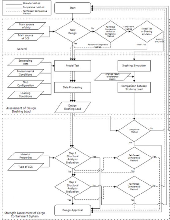
Figure 1 Flowchart of assessment of sloshing load and strength of cargo containment system
![]()
(3) Absolute Method

The absolute method is conducted through a two-step process as shown in Figure 2. The step 1 is to apply the maximum design sloshing load as the static load and to evaluate the safety. When the acceptance criteria is satisfied in the step 1, the design can be approved. If it fails to meet the acceptance criteria in step 1, the step 2 should be performed. It performs the dynamic nonlinear analysis by applying the design sloshing loads of triangular form and determine whether the analysis result meets the acceptance criteria. When it satisfies the acceptance cri- teria, the design can be approved, otherwise, the design should be started from the beginning.
Figure 2 Flowchart of 2 step absolute method
4. Equivalence
In the case that the application of this guidance is not appropriate or that the Society allow that the special method and the procedure not specified in this guidance is at least equivalent to those in effect for the provision of this guidance, it is assumed to be appropriate for the provision of this guidance.
If the other evaluation method of sloshing load is equivalent to the evaluation method of this guid- ance, the Society can approve the method as an alternative. In this case in order to verify that the evaluation of sloshing load is at least equivalent to the standard of this guidance, the related in- formations should be submitted to the Society and the evaluation method is to be consulted with the Society. From the initial design phase, the purpose to use the different method should be suffi- ciently discussed.
![]()
5. Documentation
(1) Resource for approval
Depending on the assessment method of the cargo containment system, the following materials should be submitted to the Society and to be approved by the Society. In addition, if deemed necessary, the Society may require the submission of date other than those specified below.
(A) The approval data for the comparative method performed by model test
(a) Resource for approval of the cargo containment system of the reference ship
(i) The navigation information including the date, the filling level, the ship speed and the incident wave angle
(ii) The data for comparison and analysis between the sailing sloshing load and the de- sign sloshing load
(iii) The design sloshing load of the reference ship
(b) The motion analysis data of the target ship
(i) The input data of the motion analysis(loading conditions, the draft, the metacenter height and the gravity center of ship, etc)
(ii) The model of motion analysis
(iii) The detail result of motion analysis
(iv) The analysis data of critical sea state and wave condition for the model test.
(c) The model test data of the target ship
(i) The model tank and the sensor specification
(ii) The specification of the motion generator and the data measuring system
(iii) The monitoring data of motion generator
(iv) The measured data
(v) The analysis data of the design sloshing load
(vi) The postprocessing method of the model test
(d) The structural strength data of cargo containment system of the target ship
(i) Material properties and their basis
(ii) The acceptance criteria and its basis
(iii) The structural analysis result
(iv)The comparison evaluation data for the cargo containment system of the reference ship and that of the target ship
(e) The drawing of cargo containment system and the related supports
(i) The data for type of cargo containment system
(ii) The detail drawing of representative basic model
(B) The approval data for the comparative method performed by the sloshing simulation
(a) The motion analysis data of the reference ship
(i) The Input data of motion analysis(loading conditions, the draft, the metacenter height and the gravity center of ship, etc)
(ii) The model data of motion analysis
(iii) The detail result of motion analysis
(iv) The analysis data of critical sea states and wave conditions for the model test.
(b) The model test data of the reference ship
(i) The model tank and sensor specification
(ii) The specification of motion generator and data measuring system
(iii) The monitoring data of motion generator
(iv) The measured data
(v) The analysis data of the design sloshing load
(vi) The postprocessing method of model test
(c) The CFD data of the reference ship
(i) The verification data of CFD Software
(ii) The data of critical sloshing wave condition
(iii) The CFD analysis model
(iv) The CFD analysis result
(v) The analysis data of the design sloshing load
(d) The CFD data of the target ship
(i) The verification data of CFD Software
(ii) The data of critical sloshing wave condition
(iii) The CFD analysis model
(iv) The CFD analysis result
![]()
(v) The analysis data of the design sloshing load
(vi)The data for comparison and analysis of the design sloshing load between the ref- erence ship and the target ship
(e) The drawing and the related support data of cargo containment system
(i) The data for type of cargo containment system
(ii) The detail drawing of representative basic model
(C) The approval data for the reinforced comparative method
(a) The approval data of cargo containment system of the reference ship
(i) The navigation information including the date, the filling level, the ship speed and the wave angle of incidence
(ii) The comparison data and analysis data between the sailing sloshing load and the design sloshing load
(iii) The design sloshing load of the reference ship
(b) The motion analysis data of the target ship
(i) The input data of motion analysis(loading conditions, the draft, the metacenter height and the gravity center of ship, etc)
(ii) The model data of motion analysis
(iii) The detail result of motion analysis
(iv) The analysis data of critical sea states and wave conditions for the model test.
(c) The model test data of the target ship
(i) The model tank and the sensor specification
(ii) The specification of motion generator and data measuring system
(iii) The monitoring data of motion generator
(iv) The measured data
(v) The analysis data of design sloshing load
(vi) The postprocessing method of model test
(d) The structural strength assessment data of cargo containment system of the target ship
(i) Material properties and their basis
(ii) The acceptance criteria and ist basis
(iii) The structural analysis result
(iv)The comparison evaluation data for the cargo containment system of the reference ship and that of the target ship
(e) The drawing and the related support data of cargo containment system
(i) The data for type of cargo containment system
(ii) The detail drawing of representative basic model
(D) The approval data for the absolute method
(a) The motion analysis data of the target ship
(i) The input data of motion analysis(loading conditions, the draft, the metacenter height and the gravity center of ship, etc)
(ii) The model data of motion analysis
(iii) The detail result of motion analysis
(iv) The analysis data of critical sea states and wave conditions for the model test.
(b) The model test data of the target ship
(i) The model tank and sensor specification
(ii) The specification of motion generator and data measuring system
(iii) The monitoring data of motion generator
(iv) The measured data
(v) The analysis data of design sloshing load
(vi) The postprocessing method of model test
(c) The structural strength assessment data of cargo containment system of the target ship
(i) Material properties and their basis
(ii) The acceptance criteria and its basis
(iii) The structural analysis result
(iv) The comparison evaluation data for the cargo containment system of the reference ship and that of the target ship
(d) The drawing and the related support data of cargo containment system
(i) The data for type of cargo containment system
(ii) The detail drawing of representative basic model
![]()
(2) The reference data
(A) The main source of the ship
(B) Restrictions on cargo operations, such as limiting the height of the cargo loading, cooling down speed.
(C) The layout of cargo containment system in each cargo hold
(D) The general arrangement of ship with the cargo containment system installed
(E) The design constraints of the cargo containment system
![]()